Tiếng Việt
 简体中文
简体中文 Deutsch
 日本語
日本語 한국어
한국어 ไทย
ไทย Русский
 Français
This case study presents the project to increase a transformer substation capacity from 250kVA to 630kVA (22/0.4kV) for ASUZAC ACM at VSIP1, Binh Duong. Quanganhcons performed the site survey, designed a plan to reuse the existing medium‑voltage cable, supplied and installed an outdoor 630kVA transformer, reconfigured the medium‑voltage protection (Recloser), updated metering (CT/VT), installed an MCCB 1000A and a 250kVAr capacitor bank, conducted acceptance tests and handed over to the factory. [1]
The project to upgrade the substation from 250kVA to 630kVA at VSIP1 (ASUZAC ACM) — Quanganhcons carried out the site survey, installed an outdoor 630kVA transformer, reconfigured the 24kV recloser 630A, updated metering (CT/VT), installed an MCCB 1000A and a 250kVAr capacitor bank, performed acceptance tests and handed over the works.
The preferred solution was to reuse the existing medium‑voltage underground cable Cu/XLPE/PVC 1x25mm2-24kV, provided that ampacity, insulation condition and a field report validate feasibility prior to final decision.
Who is this article for?
- Factory owner / Project management
- Technical department / Plant operations team
- Purchasing / procurement team needing equipment specifications
When to read this?
- When deciding to upgrade an existing substation instead of building new
- When preparing tenders, surveys or requests for quotes for a capacity upgrade
- When you need a checklist for acceptance and handover after an upgrade
Quick summary of the VSIP1 upgrade project
Capacity upgrade from 250 kVA to 630 kVA at VSIP1 Binh Duong, owner ASUZAC ACM, Quanganhcons surveyed, supplied and installed a 630 kVA transformer.

Upgrading capacity from 250 kVA to 630 kVA at VSIP1 Binh Duong; Quanganhcons was responsible for surveying, supplying and installing the 630 kVA transformer, configuring protection, the LV side and handover. [4][5]
The actual scope included a field survey, determining the transformer location, checking LV cable routes and LV panel configuration, configuring corresponding protection and performing acceptance testing for handover to owner ASUZAC ACM. During maintenance shifts and site surveys, accessibility to the transformer and foundation conditions must be verified before moving equipment into position.
During the site survey the minimum checks must include present load currents, grid supply capability, LV cable cross‑section and length, connection points, and the switching/disconnection capability at panels. Verify protection configuration on each LV feeder to avoid overloads after the upgrade and record the site status in a survey report.
- Check the foundation location and dimensions for the transformer; measure LV cable distances and cable routing.
- Verify actual load current on the substation, load factor and the grid supply capability at the time of survey.
- Cross‑check protection requirements: the type of relays/protection functions must be specified in technical documentation before preparing installation design.
- Prepare a field survey report as the basis for cable design, selection of cross‑sections and for acceptance after installation.
Operational warning: do not proceed with capacity upgrade if the survey shows the grid source or current connection method cannot meet operational conditions; in that case propose corrective measures or consult the distribution utility. Completion of the survey step is the basis for preparing the detailed technical dossier, price quotation and performing trial runs before handover.
Background: why the factory needs a capacity upgrade
The factory needs to upgrade the substation when measured peak load approaches or exceeds the 250 kVA rated capacity and when redundancy to move up to 630 kVA is required.

The factory should upgrade the substation when measured peak load approaches or exceeds the rated capacity of the 250 kVA transformer, or when continuous operation requires additional headroom to move up to 630 kVA. [0][0]
Technically, common causes are load growth from production line expansion, adding ovens/boilers, compressors or HVAC systems; these increase peak demand and inrush currents during motor starts. Determining the correct upgraded size requires measured hourly/yearly load curves and parameters like power factor, diversity factor and engineering safety margin.
During maintenance shifts or site surveys, real‑world signals determine the option: frequency and duration of overloads, voltage drops at the point of supply, history of breaker trips, and the transformer’s insulation test results. Upgrades can be achieved by replacing with a larger transformer, adding a parallel transformer, or refurbishing MV/LV infrastructure and distribution panels; each option must be compared for losses, supply radius and operational reliability impact.
- Check actual metered load curves: determine hourly and annual peak demand.
- Inspect transformer condition: installation date, insulation condition, overload history and insulation test records.
- Record voltage dips or breaker trips during large starts (inrush) to assess required headroom.
- Cross‑check utility connection documents/acceptance records and coordinate survey, verification and acceptance before commercial energization.
- Assess the need for added surge protection, fire safety, protection panels and SCADA when the substation scale changes.
For technical decision‑making, the main criterion is comparing measured peak demand against the transformer rated capacity, including margins for starts and maintenance; if metering data is insufficient, perform load measurements and collect power factor data before finalizing the option. When moving to design and project preparation, work with the local utility/EVN for connection assessment, approval and acceptance.
Site survey: substation, medium‑voltage cable and metering
The site survey determines whether the existing Cu/XLPE/PVC 1x25mm2‑24kV underground cable can be reused by assessing ampacity, checking CT/VT, insulation resistance, loop impedance and grounding.

Reusing the existing Cu/XLPE/PVC 1x25mm2‑24kV underground cable is only feasible when documentation and field tests confirm ampacity, insulation condition and metering system are appropriate for the post‑upgrade capacity. [8][0]
Start surveys by reviewing documentation: as‑built drawings, initial acceptance records and cable/VT/CT datasheets if available. During maintenance shifts inspect the physical condition of the cable — sheath, terminations, cable trench, protective ducts and any signs of moisture or flooding.
Mandatory electrical tests include insulation resistance measurement with a Megger, loop impedance tests, phase/loop impedance and continuity checks of terminations. If insulation damage is suspected perform partial discharge testing or high‑voltage tests per professional procedures.
- Check utility/EVN acceptance records and cable/VT/CT datasheets; document all discrepancies in the field survey report (ohm measurements, insulation tests, photos).
- Visual inspection: sheath cracks, overheated/charred terminations, corrosion or partial discharge marks require intervention.
- Measure load current and power factor at the time of survey to compare with rated ampacity from datasheets and buried conditions.
- Assess actual ampacity according to installation conditions (single burial, cable grouping, ambient temperature); if ampacity is insufficient, replace cables or redistribute load.
- Check CT/VT and metering: determine accuracy class, current range and CT ratio suitable for post‑upgrade currents; if unsuitable, replace CTs or adjust metering scheme.
- Check grounding and lightning protection: measure earth resistance, verify armor/metal sheath bonding and the station lightning system condition.
- All measurements must be recorded in signed reports with calibration/certification of measuring instruments.
In the field, every technical finding must be documented with photos, location and measured values as the basis for deciding to reuse, refurbish or replace. After completing connection changes or capacity upgrade, schedule a load test, measure voltage regulation and monitor transformer temperature.
Operational warning: do not energize loads beyond cable or protection capacity without signed measurement reports and confirmation from the utility; any metering scheme changes must be accepted as per the current procedures.
Technical option: upgrade vs build new
Prioritize upgrading when the existing substation infrastructure meets structural, ampacity, cooling and acceptance process requirements with the utility.

Upgrading reuses the existing substation structure by replacing or extending the transformer, whereas building new installs a completely new substation on a new foundation with new equipment. [0][0]
From compliance and technical perspectives, the upgrade decision must start with verifying transformer acceptance records, insulation test reports, earth resistance results and CT/VT parameters. On site measure LV cable ampacity, check safety corridors, clearances and cooling capacity around the transformer; if any of these factors fail, building new is often the safer option.
Minimum field checklist includes:
- Transformer technical dossier and previous acceptance reports, insulation test results.
- Structural load capacity of foundation and panel frames (check bearing pressure, compartment dimensions).
- Ampacity of MV and LV cables, MV‑LV connection conditions and busbar capacity.
- Cooling/ventilation capacity, ventilation clearances and required cooling upgrades if needed.
- Protection system: relays, recloser, thermal relays, and coordination with the network protection.
- Measures to minimize supply interruption during transformer swap (outage scheduling, load transfer procedures).
Operational warning: do not increase capacity if cable ampacity or cooling capability has not been verified; during maintenance have a load test and switching plan to limit downtime. Procedurally, all capacity changes must be coordinated with the utility/EVN under the connection and acceptance process.
Light conclusion for the next step: when documentation and field checks allow it, upgrading is usually less costly than building new; if data is missing, structural or ampacity limits exist, switch to a new build option and prepare detailed acceptance and engineering calculations before execution.
Reusing existing medium‑voltage underground cable: checks and conditions
Evaluate the condition of the 1×25 mm2 XLPE/PVC 24 kV underground cable to determine whether it can supply a 630 kVA transformer under real site conditions.

The 1×25 mm2 underground cable can only continue in service for a 630 kVA transformer if the ampacity adjusted for field conditions meets the expected load current and insulation plus terminations show no severe degradation; otherwise supplementation or replacement is mandatory. [16][17]
Field procedures must include conductor resistance measurement, insulation resistance (IR) before and after any intervention, joint inspection and mechanical inspection of the cable trench. During maintenance perform partial discharge (PD) testing if equipment is available and thermal monitoring during a trial run; all measurements should be compared with the original acceptance records.
- Document checks: route drawings, acceptance records, joint reports and field photos.
- Electrical tests: conductor resistance, IR before/after repair, PD survey if possible.
- Mechanical inspection: excavate suspect areas, observe insulation cracks, water ingress in the trench, corrosion of armor or sheath damage.
- Installation conditions: measure burial depth, distance to other ducts, number of parallel cables and ground/soil temperature influence.
- Grounding tests: check armor/metal sheath bonding and earthing of cable/station panels.
On‑site decision criteria must rely on measured results: rated ampacity must be corrected for burial conditions, grouping and soil temperature; if the adjusted ampacity is greater than or equal to expected load current and IR, PD, and joints are acceptable then reuse may continue with mitigation (temporary loading limits, thermal monitoring); if IR is significantly reduced or PD/joints show severe damage, prioritize cable replacement.
Operational warning: medium‑voltage joints are high‑risk points and must have joint records and contact resistance measurements; water in the trench, sheath cracks or PD detection are sufficient reasons to require immediate replacement. At acceptance and trial stages all capacity or connection changes must be notified to and accepted by the responsible EVN/distribution utility.
Action conclusion: perform IR, PD and thermal measurements during a load run, provide joint documentation and route drawings to the evaluator, and specify temporary measures or replacement based on measured results to reach a final decision.
Installing an outdoor 630kVA transformer on a foundation
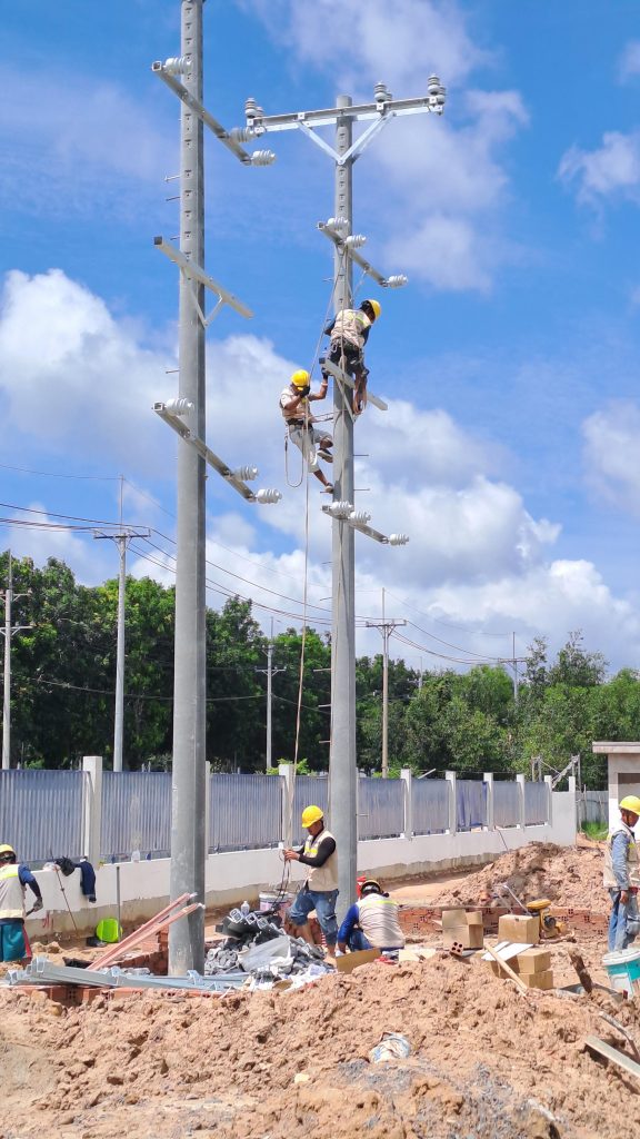
Installing an outdoor 630 kVA transformer in place of a 250 kVA unit requires assessment of positioning, a reinforced concrete foundation, grounding and proper MV/LV connections. Collect detailed transformer specs (weight, dimensions, lifting points, cooling type, %Z, vector group) and survey the site prior to foundation design and connection planning. Cooling, oil containment, lightning protection and coordination with the utility acceptance process are mandatory steps before execution.

The main requirements when replacing a transformer are to ensure foundation strength, earthing and clearance for cooling consistent with the new transformer’s size, weight and cooling method. In practice failing to verify required operating parameters and the actual mass can overload the foundation or hinder lifting operations. [3][2]
Before any execution collect the full spec sheet: rated power, HV/LV voltages, short‑circuit impedance (%Z), vector group, cooling type (ONAN/ONAF), weight, dimensions and lifting point locations. On site check foundation elevation, existing bearing capacity and surrounding density to determine if foundation reinforcement or repositioning is needed.
Field checks and acceptance criteria should include:
- Verify actual transformer weight and dimensions against foundation design; check concrete bearing capacity and any piles if present.
- Inspect oil containment trenches/ pits and oil containment measures to prevent spills for outdoor transformers.
- Measure earth resistance after earthing network installation linking transformer tank, foundation frame and busbars; retain acceptance records for coordination with EVN as required.
- Check safe clearances around the transformer for natural cooling and maintenance access, and confirm access for testing and repair works.
MV 22 kV and LV 0.4 kV connections must follow coordination with the utility/EVN regarding switching points, cable materials and safety clearances. During maintenance and acceptance have electrical test records and grounding confirmation from authorized acceptance bodies.
Practical warnings and decisions: do not position the transformer if the foundation has not been certified as structurally adequate; do not connect MV until approval or an approved cable routing plan is obtained from the utility/EVN. If there is doubt about cooling type (ONAN vs ONAF) or %Z parameters request the official manufacturer spec sheet and perform ambient temperature surveys at the location to ensure cooling matches manufacturer recommendations.
The next step for decision makers is to conduct a site survey, collect the full 630 kVA transformer spec sheet, and initiate utility acceptance coordination before designing the foundation and cable routes.
Reconfiguring the 24kV recloser 630A, LBFCO, CT/VT and metering
Configure the 24kV 630A recloser, adjust LBFCO/fuses, check/add CTs and review VTs to ensure selectivity and compliance with metering regulations.

It is necessary to reconfigure the 24kV 630A recloser, adjust LBFCO/fuses, check or add CTs and review VTs, and recalibrate metering settings to ensure selectivity and regulatory compliance. [13][0]
To validate this requirement gather actual inputs: existing recloser functional acceptance records, short‑circuit diagrams at site, load characteristics after upgrade to 630 kVA and the present CT/VT connection diagram. On site, engineers must measure no‑load currents, identify CT/VT connection points and check LV cable ampacity before deciding to change LBFCO or CT ratios.
Work sequence with separate acceptance records for each step:
- Field survey and collection of recloser test records, circuit diagrams and load data.
- Check existing CT/VT: measure errors, insulation, overvoltage tolerance; assess whether VT 12kV/120V can be reused or must be replaced.
- Determine recloser settings (pickup, curve, time dial, reclosing count, lockout, earth‑fault pickup/time) for both main and backup scenarios.
- Adjust LBFCO/LV fuse sizes if needed based on cable ampacity and short‑circuit capacity; add CTs with appropriate ratios to cover the operating current range for protection and metering.
- Perform functional tests after adjustments: overcurrent, earth‑fault, reclosing, check RTU/SCADA and review event logs.
- Prepare acceptance records: recloser functional test, CT/VT verification and meter/measurement adjustment records per EVN procedures.
High‑level scope summary table:
| Item | Description | Points to check |
|---|---|---|
| Recloser | Configure pickup/time/reclose and protection curves for two substations. | Settings table, functional tests, event log, selectivity with upstream/downstream protection. |
| LBFCO / LV fuses | Evaluate and change fuse sizes according to load and short‑circuit conditions. | Cable ampacity, short‑circuit capability, unwanted trip impact. |
| CT | Add or replace CTs with appropriate ratios (e.g. to cover 65/130A range if required). | Operating range, accuracy for protection and metering, CT placement in the scheme. |
| VT | Review existing VT 12kV/120V for accuracy and insulation before reuse. | Voltage accuracy, phase, overvoltage tolerance, replace if out of spec. |
| Metering | Adjust meter/CT/VT configuration to ensure correct indirect metering per regulations. | Calibration records, compliance with Measurement Law and EVN procedures before acceptance. |
Key technical decisions and operational warnings: choose CT ratios that cover the operating current range to avoid protection saturation or blind spots; LBFCO/fuse sizing must consider cable ampacity and fault current to avoid unnecessary trips. If VT is reused, provide verification of accuracy and insulation before connecting to metering circuits.
All changes must be documented with recloser functional test reports, CT/VT calibration reports and meter adjustment records; during maintenance preserve event logs and confirm RTU/SCADA before acceptance. To finalize settings and perform EVN acceptance studies, a full field survey and short‑circuit/load data collection is required.
Low‑voltage side: MCCB 1000A, protection relays, LV cables and 250kVAr capacitor bank
Choose MCCB 3P‑1000A, overcurrent/earth‑fault relays, LV cable 1x240mm2 and a 250kVAr capacitor bank based on load current, fault current and power factor targets.

The MCCB 3P‑1000A is specified as the main LV breaker because it must withstand high inrush and fault currents after the upgrade; breaking capacity (Icu/Icw) must exceed the prospective fault current at the panel. On site measure the actual fault current after connection to confirm breaking capability and update protection parameters. [1][0]
Protection relays must provide overcurrent and earth‑fault functions with appropriate time‑current characteristics; use separate digital relays or MCCBs with integrated trip units, provided there are alarm contacts for SCADA and adjustable parameters. During site surveys verify that relays support phase unbalance functions and have alarm outputs for the monitoring system.
Select the LV cable 1×240 mm2 based on actual ampacity for the installation method (conduit or tray), grouping factors, temperature correction and conductor material. In maintenance or survey shifts it is mandatory to re‑measure voltage drop and check cable lengths to ensure allowable voltage drop and temperature limits are not exceeded.
The 250 kVAr capacitor bank is proposed to compensate reactive power and improve plant power factor; choose fixed or automatic switching type based on load distribution and cosφ targets. Required items for the capacitor bank include step switching controller, overcurrent protection for capacitors, fuses/breakers per capacitor step and voltage/phase protection; during acceptance measure cosφ before and after, measure delivered kVAr and check capacitor insulation.
- On‑site check: measure prospective fault current at the panel after the upgrade.
- On‑site check: verify cable ampacity according to installation and grouping factors.
- Acceptance tests: measure cosφ before/after, measure actual kVAr delivered by the capacitor bank and check system voltage drop.
- Operational warning: coordinate acceptance and connection with the local utility/EVN.
| Item | Check point | Notes |
|---|---|---|
| Main MCCB | Compare Icu with prospective fault current | Field measurement required after installation |
| Protection relays | Check overcurrent/earth‑fault functions and alarm outputs | Adjust time‑current characteristics |
| 1×240 mm2 cable | Check ampacity, voltage drop and installation conditions | Consider grouping and ambient temperature |
| 250 kVAr capacitor bank | Measure compensation performance, check capacitor protection | Choose fixed or automatic based on load profiles |
Light conclusion: equipment selection must rely on actual field measurements and coordination with EVN; the next reasonable step is to prepare a measurement list (hourly load profile, prospective fault current, cable lengths, ambient temperature) to finalize equipment specifications and protection settings.
Technical checks, acceptance testing and handover
The acceptance procedure for a capacity upgrade must confirm safe connections, electrical tests, protection checks and prepare complete acceptance documentation.

Acceptance must confirm safe connections, compatibility of equipment after the capacity increase (250 → 630 kVA) and safe operation at energization. [0][0]
Before acceptance verify mechanical aspects, cable terminations and earthing; during maintenance or site survey measure insulation resistance, check insulating oil and mechanical fixings. Minimum checks to list for acceptance are:
- Mechanical checks: transformer positioning, anchoring, insulating oil condition (if oil replaced provide laboratory analysis report).
- Cable/termination and earthing checks: measure earth resistance, inspect joints, check lightning protection and temporary earthing during construction.
- Basic electrical tests: insulation resistance (Megger), winding resistance, CT/VT ratio checks if CT/VT changed, ratio and polarity tests.
Protection and control checks must include relay configuration, functional tests for overcurrent, earth‑fault, unbalance and coordination between relays and breakers. After energization prepare observation records of phase voltages, inrush currents, initial oil temperature and audible vibration/noise.
Acceptance documentation must include detailed test reports with results, energization record, construction log, factory certificates of equipment and as‑built connection diagrams. For connections to the distribution network follow the acceptance and energization procedures defined by the utility/EVN.
Operational warning: all acceptance records must specify responsibility for remediation, completion deadlines and whether the report is provisional or final; if testing data or factory certificates are missing do not perform official handover. To finalize acceptance collect full field survey data and detailed electrical test records before creating the handover report and maintenance logbook.
The upgrade project from 250kVA to 630kVA at VSIP1 secures the required power capacity for ASUZAC ACM production. The next step for the factory is to request a detailed site survey, verify cable/electrical parameters and prepare construction documentation and protection adjustments before signing an execution contract.
Frequently asked questions
When should a factory upgrade the transformer substation from 250kVA to 630kVA?
When measured peak load approaches or exceeds 250kVA, frequent voltage drops occur or there is a planned equipment expansion. Principle: base the decision on measured load curves, inrush currents and fault level. Collect load, inrush and utility data before deciding.
How is upgrading a substation different from building a new substation?
Upgrading reuses existing infrastructure, usually faster and cheaper but constrained by foundation, cables and protection. Building new allows optimal layout and capacity but requires more time, cost and procedures. Compare costs, time and field conditions to decide.
Can existing medium‑voltage cable be reused when upgrading?
Yes if the cable meets ampacity, insulation and joint condition requirements, but a mandatory field check is required: Megger IR, loop impedance, joint inspection and mechanical condition. Need cable datasheet, test results and burial depth information to conclude.
Why must the 24kV 630A recloser be reconfigured?
It must be adjusted to accommodate new fault levels and load characteristics, ensuring protection selectivity between the substation and the grid and avoiding trips caused by inrush. Perform a short‑circuit study, load curves and prepare a recloser settings table (pickup, time, reclosing) for accurate adjustment.
What are the roles of MCCB 1000A and protection relays after upgrading to 630kVA?
The MCCB 1000A is the main LV breaker for isolation and to withstand fault currents; protection relays detect overcurrent/earth‑fault and coordinate with the recloser for selectivity. Size and breaking capacity must be based on expected fault currents and measured load curves; short‑circuit data is needed for correct selection.
What does a 250kVAr capacitor bank do for the factory?
The capacitor bank improves power factor, reduces reactive power demand from the grid, lowers losses and reduces the risk of power factor penalties; it also reduces transformer loading and stabilizes voltage. Before installation assess current cosφ, harmonic profile and switching strategy to optimize effectiveness.
Short checklist for owners before requesting a capacity upgrade
- Prepare existing substation documentation: current transformer capacity, connection diagram, previous acceptance reports if any.
- Provide substation location, MV/LV cable drawings and existing VT/CT information to the contractor for survey.
- Permit site survey to check underground cables (ampacity, insulation condition, burial/terminations condition).
- Request a report on recloser protection adjustments and protection functional diagrams for both substations.
- Prepare the site for an outdoor 630kVA transformer (foundation, earthing) and confirm LV cable routing.
- Check metering requirements, list CT/VT to be replaced/added and meter configuration per EVN regulations.
- Prepare acceptance documentation: electrical test reports, equipment certificates, construction logs and handover documents.
Contact the Quanganhcons technical team for a free site survey and technical consultation, equipment list and a tailored acceptance checklist for your factory substation.
References (18)
This article is based on verified project data provided in the input (transformer, recloser, CT/VT, existing cables) and cites official public sources for standards, regulations or acceptance requirements. Prefer government/EVN, legal documents, TCVN/IEC/ISO/IEEE references; each technical claim should include a link or technical note for traceability. Do not use vendor materials as standards without official citation; do not publish price or confidential test records not present in the verified input.
-
Legal library / Circular (standardization documents) | TCVN repository — PDF related to standards/regulations | tcvn.gov.vn | 2026
Official source from tcvn.gov.vn used to verify mentioned technical requirements or regulations.
-
Guidance on TCVN application regarding electrical vehicles
Standard/regulatory document referenced for technical requirements in the article.
-
Guidance on TCVN for electrical distribution modules
Standard/regulatory document referenced for technical requirements in the article.
-
National Standards Index (Final)
Standard document used to cross‑check technical requirements mentioned in the article.
-
National Standards Index (Final)
Standard document used to cross‑check technical requirements mentioned in the article.
-
tighten EV charging station standards to ensure safety from design to operation
Standard/regulatory guidance referenced in the article.
-
Standards for energy sources to maintain sustainability
Standard/regulatory guidance referenced in the article.
-
EVN technical guidance for connection and documentation (PDF)
Official EVN guidance used to verify technical and acceptance requirements cited.
-
Circular 2025 on distribution and metering systems
Official EVN document referenced for metering and distribution rules.
-
EVN implementation guidance
Official EVN guidance referenced for technical procedures.
-
EVNHCMC information protection policy
Utility policy documentation referenced.
-
EVN regulation on electricity services
Official EVN regulation referenced for acceptance procedures.
-
EVNSPC commercial procedures
Regional EVN procedures used to verify business and technical steps.
-
EVNSPC official guidance or documents
Utility documents referenced for verification.
-
Circular regulating distribution and metering systems
Official EVN circular referenced for metering and distribution rules.
-
Government Gazette policy information
Official policy reference used in the article.
-
Government policy information
Official policy reference used in the article.
-
Government policy information (archive)
Official policy reference used in the article.