
 Tiếng Việt
 简体中文
简体中文 Deutsch
 日本語
日本語 한국어
한국어 ไทย
ไทย Русский
 Français


This case study presents the project for the 22kV line and a 400kVA transformer for Phu Viet Rubber factory at Lot LB2, Xuyen A Industrial Park (Long An). Quanganhcons was contracted to execute the full 22kV line installation, supply and install the Thibidi 400kVA transformer, pull approximately 600m of low-voltage cable to the workshops, equip the installation with a 630A main MCCB and a 160 kVAr capacitor bank; the project was accepted, energised and handed over on 26/06/2021 at 15:00. [1]
The project was the 22kV line and a 400kVA transformer installation for Phu Viet Rubber factory at Lot LB2, Xuyen A Industrial Park (Long An).
Quanganhcons delivered the full 22kV line works, supplied/installed a Thibidi 400kVA transformer, pulled ~600m of low-voltage cable and completed acceptance and energisation on 26/06/2021 at 15:00.
Who is this article for?
- Plant owners and project management
- Plant technical/maintenance teams
- Procurement and tendering departments
- Supervision consultants and site installation crews
When to read this article?
- When evaluating a contractor’s capability to deliver a 400kVA substation
- When preparing for acceptance, energisation or 22kV connection
- When preparing tender documents/technical requirements for a 400kVA substation
Project summary: 400kVA at Phu Viet Rubber
Overview of the transformer project: 400 kVA at Xuyen A Industrial Park (Long An), scope covering LV electrical works and the energisation milestone on 26/06/2021.
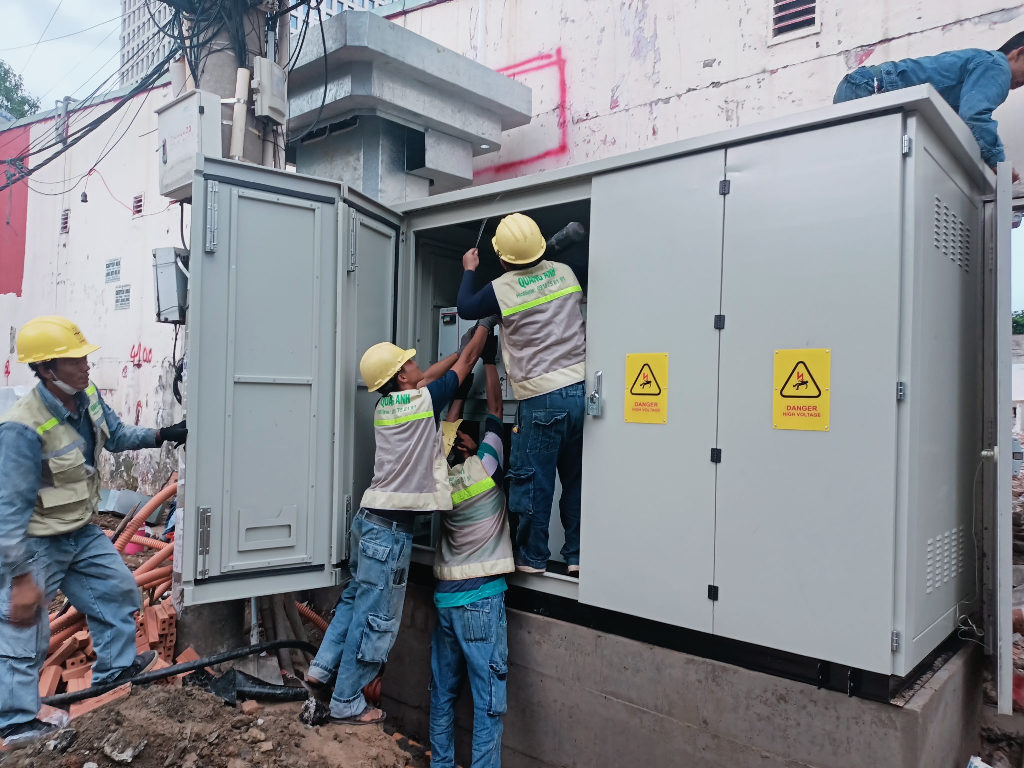
The 400 kVA transformer for Phu Viet Rubber was energised on 26/06/2021; the project scope per documents included the MSB/DB panels, power and control cables, lighting, earthing and the capacitor bank. [0][0]
Site location: Xuyen A Industrial Park, Long An province. The implementing contractor/partner recorded in the project documents is Quanganhcons / Quanganhcgte. The substation capacity in the documentation is 400 kVA, to be operated with a single low-voltage transformer as detailed in the project files.
During site survey and in the maintenance shift before/after energisation, the following items must be checked:
- Earthing verification: measure earth resistance using on-site field methods and compare against acceptance criteria in the test report.
- Insulation resistance: test the transformer windings, power cables and control cables before no-load trials.
- No-load and load testing: carry out transformer acceptance tests in sequence, monitor inrush currents and temperatures.
- MSB/DB and protection function checks: confirm relays/CBs operate correctly, wiring matches the as-built drawings and protection settings are tuned.
- Capacitor bank checks: verify reactive power rating, control/automatic switching, and overcurrent/isolation protection.
The energisation record (milestone 26/06/2021), the electrical safety acceptance report and the quality acceptance report are the official handover documents; when publishing this data online or in internal reports attach scans or links to the acceptance records. Note: this is a historical event from 2021 — when citing standards or official letters, distinguish the version applied in 2021 from the current version.
Practical risks include missing acceptance documents, incomplete verification of protection devices or missing contract cost data; the next reasonable step is to request the energisation report and the equipment list to perform site checks or verify acceptance documentation.
Context: power needs for a rubber manufacturing plant
A dedicated 400 kVA transformer was selected for the Phu Viet Rubber plant to ensure continuous supply for large motors, compressors and production lines.
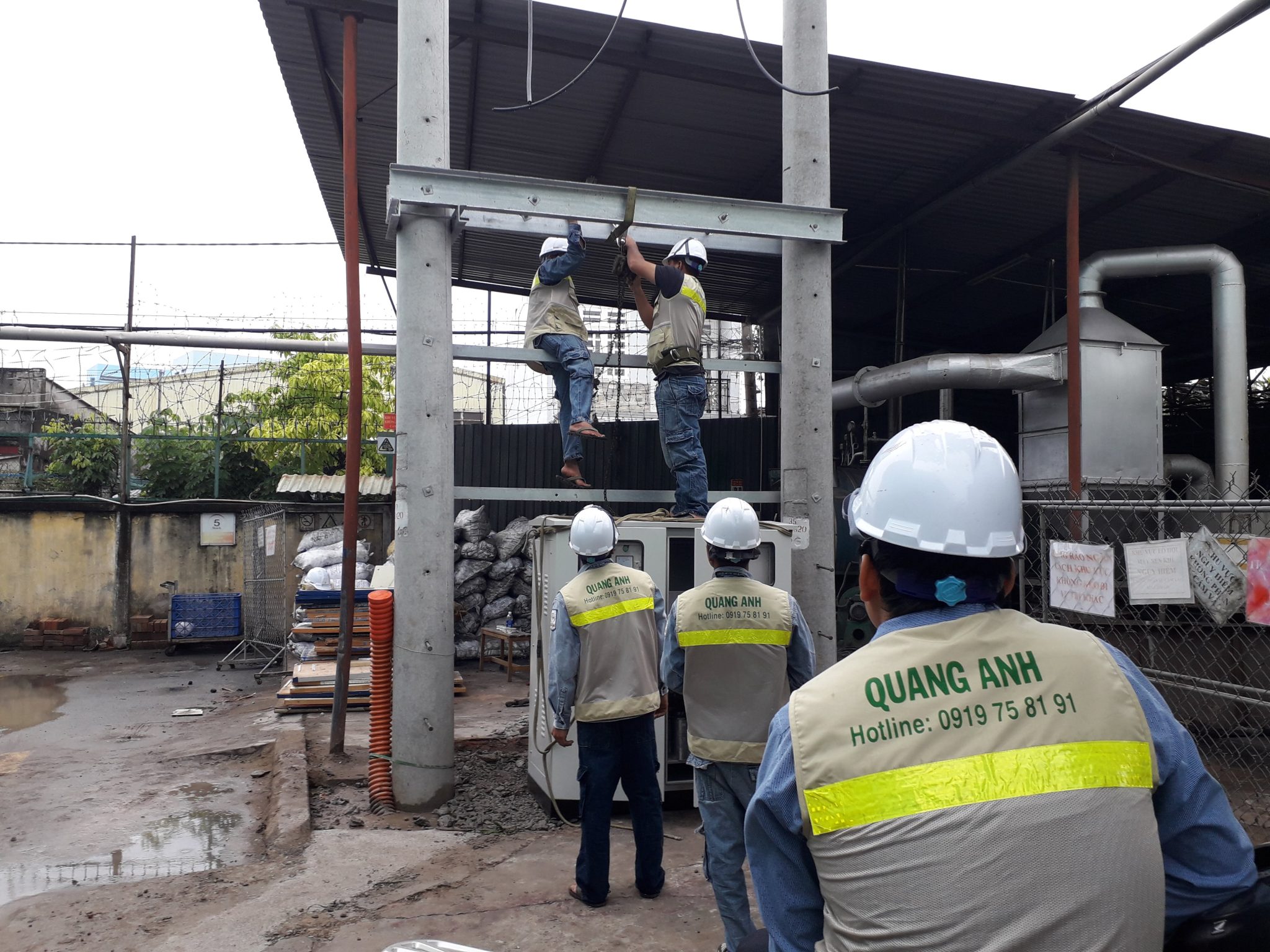
A dedicated 400 kVA unit suits Phu Viet Rubber because it provides a separate supply for large industrial loads, reducing the risk of overload from the shared distribution network. [4][18]
Technically, the transformer rating is chosen based on total rated load, motor starting currents, actual power factor and diversity factor; these determine peak demand and required reserve capacity. During site survey measure/verify actual loads and supply voltage to determine the correct rating; remember the project documents are historical (2021) so verify all detailed parameters on site.
A dedicated substation reduces voltage drop, limits voltage fluctuation and improves power quality for sensitive equipment such as motors and inverters, especially when combined with a power factor correction cabinet to improve cos φ. For connection procedures and tariffs, comply with the distribution utility (EVN) customer connection guidelines and regulations for dedicated transformers (note: rules differ for dedicated transformers ≥25 kVA). Operational safety includes earthing, lightning protection, safe clearance and a maintenance plan compliant with standards/TCVN and pre-energisation checks (insulation, earthing, protection function).
- Field checks: measure rated and peak loads, measure voltage at the connection point, check capability of the 22kV/0.4kV feeder or the point of connection.
- Design criteria: determine diversity factor, motor starting currents, existing power factor and growth margin to size a 400 kVA transformer appropriately.
- Power quality: assess reactive power compensation needs and measures to reduce interference to inverters/motors.
- Procedures: coordinate early with EVN/local power company to define connection route, technical requirements and applicable tariff.
Operational warning: do not energise until earthing acceptance and protection function tests are complete; also ensure reserved capacity for simultaneous starts and future production growth. Combine site survey results and EVN coordination to finalise transformer sizing and connection procedures.
Site survey at Xuyen A Industrial Park
The site survey at Lot LB2, Xuyen A IP identifies the transformer location, 22kV connection point, LV cable route and risks to address before construction.
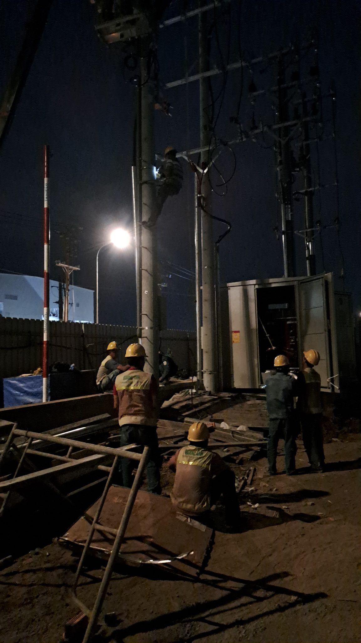
The transformer location was identified as Lot LB2; the preliminary survey recorded lot boundaries, available area and distance to adjacent structures which require detailed measurement before execution. [0][0]
On site, inspect the 22kV connection point to identify the line owner, pole or suspension frame location, the existing phase arrangement and the feasibility of obtaining an earth connection. During the survey confirm whether the medium-voltage line is live and verify the connection agreement with the network operator (EVN) as per project files.
The LV cable route survey should describe expected route length, the cable way (tray, trench, duct or through slab) and obstacle crossing points; also check pole/foundation construction conditions including ground stability, piling feasibility and access for construction vehicles. For earthing, record planned earthing rod positions and propose a field earth resistance measurement if none exists.
- Field check criteria: Lot LB2 boundary, transformer pad area, distance to adjacent structures, MSB/DB location and working clearances.
- 22kV connection point: verify line owner, pole/frame location, phase diagram and capability to take an earth connection; require connection documents (application, location drawing, wiring diagram, transformer 400 kVA datasheet, expected load, EVN connection agreement).
- MV safety corridor: record distances to poles, trees and buildings; check local clearance requirements before piling or erecting poles.
- LV cable route: specify cable routing method, obstacle crossings, usability of existing trays/ducts and slab-piercing locations.
- Earthing and foundations: recommend earth resistance measurement, check earthing rod locations, distance to other metallic systems; assess ground stability and piling feasibility, order geotechnical survey if ground is weak.
- Construction safety: check traffic flow, access for construction vehicles, water sources, flood risk and turning space for cranes/large vehicles.
- Fire safety and security: identify fencing, warning signs, station locking and ventilation if PFC is installed in the station room.
On-site warnings: live MV lines, trees or poles within the corridor, weak ground and obstructions along the cable corridor are risks to mitigate before works. During maintenance/works establish barriers, coordinate with the line owner for isolation of the working section and prepare flood mitigation if the area is flood-prone.
Interim conclusion: the site survey listed main checks and risks; to finalise the transformer location, cable route and earthing design perform detailed on-site measurements (coordinates, earth resistance, ground stability) and complete the connection documentation with EVN.
22kV line and 400kVA substation scheme
The 22kV connection scheme for a 400 kVA substation outlines the choice of single or double circuit, transformer location, pole type and EVN acceptance requirements.
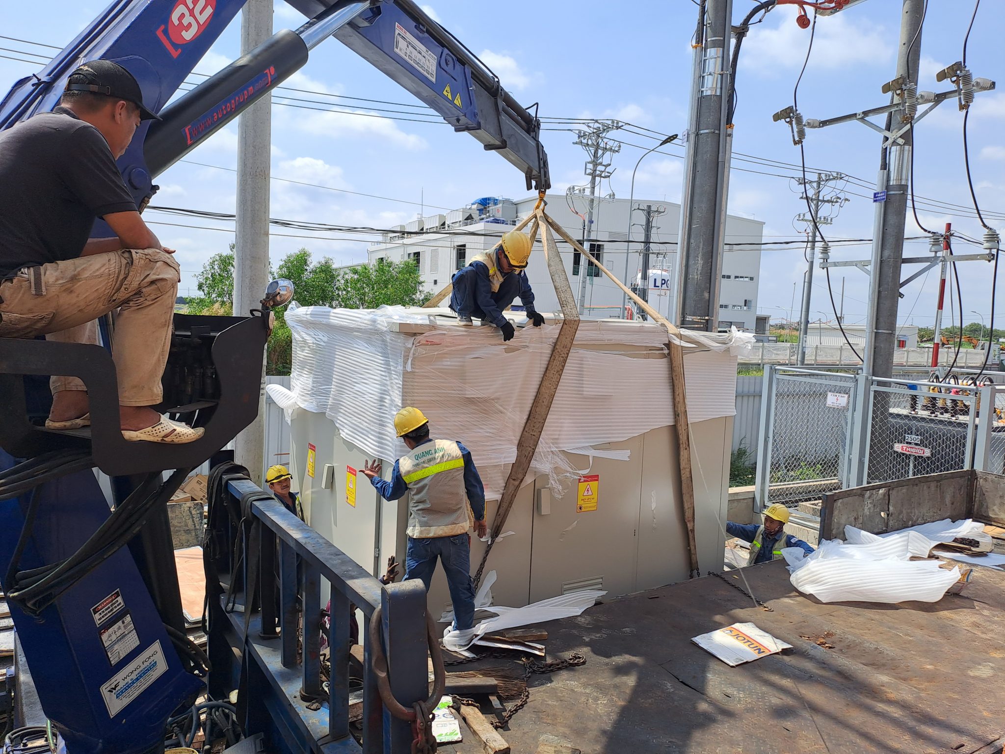
The 22kV MV connection for a 400 kVA substation commonly chooses a single or double circuit depending on load criticality and reliability requirements, and must meet the acceptance criteria of the power utility/EVN. [12][9]
During the plant survey decide the transformer siting (outdoor, unattended) based on safe clearance to nearby structures, crane access for future replacement, and ease of maintenance. Record in the site survey the 22kV route length to the connection point, foundation soil conditions for poles and distance to the existing 22kV route.
Regarding the connection diagram, the 400 kVA substation is linked into the 22kV network at the MV cabinet (sectioning unit); determine whether single or double circuit is chosen, neutral connection point and positions of switching devices (fuses/OLR/MCCB if present). Overhead conductors or CV/CXV cables can be used in practice; the type and conductor size (e.g. CV/CXV 25 mm2 reference) must be verified against project documents prior to acceptance planning.
| Transformer siting criteria | Requirement / Field check |
|---|---|
| Safe clearance to nearby structures | Measure on site; record distance from transformer center to nearest structure in the survey report. |
| Equipment access | Ensure crane access and concrete pad bearing capacity; verify during maintenance shift. |
| Proximity to existing 22kV route | Verify connection point location and cable/overhead routing option (overhead or underground). |
Choice of pole type (concrete or steel) depends on route length, ground conditions, crossing of roads/rivers and the site survey. Generally, double-circuit is preferred for factories or critical load areas; single-circuit can be acceptable with appropriate protection and SLA measures.
MV safety procedures must include isolation and temporary earthing before works, warning signage and area barricades. During maintenance verify isolation first, measure temporary earth resistance and confirm absence of MV voltage before working.
- Minimum pre-energisation checks: measure earthing resistance, test cable insulation, verify neutral connections and check the earthing scheme.
- Switching and relay tests: schedule formal coordination with the utility and perform switching tests as required for acceptance.
- After energisation: monitor connector temperatures at no-load, check for oil leaks if oil-filled transformer, and observe the operation of isolators.
Acceptance documentation with EVN/power company typically includes: connection agreement documents (single-line diagram after the point of connection including 0.4/22 kV diagram), technical acceptance report, insulation test results, earthing resistance measurements, switching test records and as-built drawings. Switching coordination for energisation must be scheduled officially and an acceptance report completed before operation.
Operational warning: all statements about conductor sizes, protection devices or transformer models must be verified against the project files; do not energise if earthing or insulation measurements fail. Check neutral earthing to avoid circulating currents between the plant and distribution network.
Next steps for operations: prepare the as-built documentation and equipment certificates before handing the substation to network management, schedule routine maintenance and plan on-site MV safety inspections.
Main materials and equipment supplied
Verified equipment list: Thibidi 400 kVA transformer; CV/CXV 25 mm2 MV cable; LV cables 511 m (150 mm2) and 56 m (185 mm2); Mitsubishi 630 A MCCB; 160 kVAr PFC cabinet.
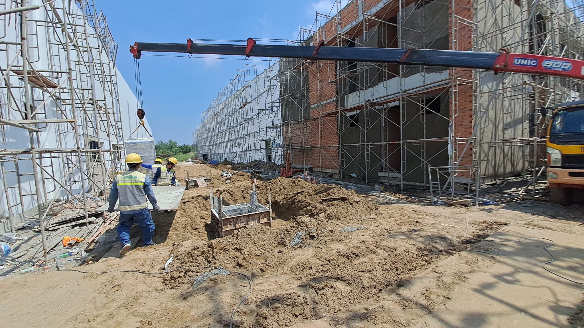
The verified equipment list for the project included: Thibidi 400 kVA transformer; CVX/CV medium-voltage cable 25 mm2; LV cable runs of 511 m (150 mm2) and 56 m (185 mm2); Mitsubishi 630 A main MCCB; 160 kVAr power factor correction cabinet. These items are taken directly from the verified project data; other protection equipment are listed only if confirmed in the documentation. [0][0]
Acceptance and compatibility checks should focus on providing catalogues/spec sheets, type test certificates and FAT reports for each item. In the field, measure short-circuit values at the point of connection to verify MCCB/MV breaker selection and to size/configure the capacitor bank; if short-circuit data is missing, protection selection and capacitor staging can only be made as provisional scenarios.
Summary table of main materials per verified documentation:
| Equipment | Specification per documents | Field check notes |
|---|---|---|
| Transformer | Thibidi, 400 kVA | Verify catalogue, rated voltages (if in documents), FAT |
| MV cable | CV/CXV, 25 mm2 | Check insulation sheath material, signs of mechanical damage |
| LV cable | 511 m — 150 mm2; 56 m — 185 mm2 | Measure conductor resistance continuously, inspect terminations on installation |
| Main MCCB | Mitsubishi, 630 A | Verify trip tests, coordination characteristics |
| PFC cabinet | 160 kVAr | Require catalogue; confirm stage configuration before acceptance |
Checklist of documents to submit before energisation (during acceptance/trial run):
- Catalogue / spec sheets for transformer, MCCB, PFC cabinet, cables.
- Type test certificates and FAT reports for transformer and PFC cabinet if available.
- Installation testing reports (megger, earthing checks, contact resistance measurements).
- As-built wiring diagrams and control circuit diagrams for PFC/MCCB.
- Short-circuit study or on-site short-circuit measurement results for protection coordination.
- Approval documents from the investor / EVN where MV connection requires utility consent.
Operational warning: do not energise a capacitor bank before verifying harmonic levels and stage configuration, as this affects capacitor life; during maintenance check residual currents/harmonic content before isolating or changing fuses. Material supply responsibility lies with the contractor per the verified list; all MV connections must follow approval procedures of the investor/EVN when required.
Works: poles, MV equipment, earthing and station panel
Sequence of works for reinforced concrete pole foundations, MV equipment installation, earthing system installation and completion of station panels (MSB/MCCB, PFC) with field safety checks.
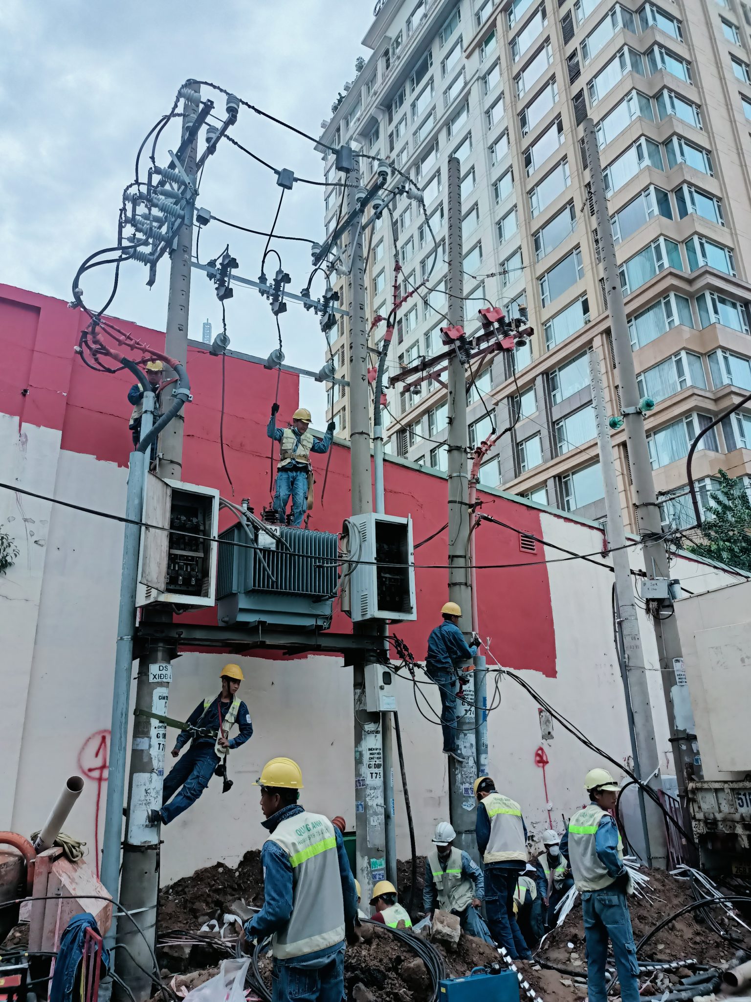
Works for poles, MV equipment installation, earthing system construction and station panel completion must follow a sequential workflow: position surveying, foundation works, pole erection and anchoring, equipment installation, and earthing checks before acceptance. [12][15]
On site start with layout and peg placement per drawings, then build pole foundations (dimensions and depth per geotechnical survey), provide anchor plinths to resist overturning and settlement and allow burial depth for neutral/earthing conductors.
- Mechanical works for poles: excavate foundations, cast base plinth, install anchor bolts, check verticality and torque bolts per manufacturer’s moments.
- Pole erection and anchoring: lift and secure poles, ensure safe lifting procedures and guying, check mechanical contacts at support frames.
- MV equipment installation: arrange switchgear, isolators, busbars and capacitor bank (if any) per manufacturer clearances and creepage distances.
- Station panel completion: install MSB/MCCB and PFC cabinet; arrange neutral busbar, internal wiring, panel earthing and fit appropriate protective devices.
- Earthing works: create a ring earth around the station, drive earth rods around the perimeter, and connect the main earthing bar to equipment enclosures, pole frames and transformer neutral.
- Testing and acceptance: measure total earth resistance, single rod resistance, use fall-of-potential for ring earth, perform insulation resistance (megger) tests between phases and earth and test relay/protection functions before energisation trials.
During works and acceptance maintain safety measures: cordon off the area, implement lockout/tagout, post warning signage, provide PPE (helmets, insulating gloves, safety harness) and have a safety officer supervising elevated or electrical tasks.
- Field checks: tighten bolts, inspect mechanical contacts, megger test phase-to-earth insulation, test relay/protection functions.
- Earthing checks: measure system earth resistance (Ω), single rod resistance, fall-of-potential for the ring, and step & touch potential tests where the station borders public areas.
- Lightning protection: install neutralising rods and down conductors connected to the earthing system, ensure separation between down conductors and signal cables.
Record all works comprehensively in the site log: test reports, earthing measurement results, photographic evidence and updated as-built drawings; the occupational safety acceptance report is a precondition for energisation trials.
Operational warning: field earthing results may vary by rainy season; use calibrated instruments and ensure the work area is isolated before operations. After mechanical-electrical acceptance proceed to trial energisation and monitor protection functions during the initial operation period.
Pulling approximately 600m of low-voltage cable to workshops
The cable scope comprised 511 m of 150 mm² and 56 m of 185 mm² LV cables; works include pulling, mechanical protection and post-installation electrical testing. Choose a pulling method suitable to the route (pull points, bend radii, trays, ducts) and respect the cable’s maximum pulling tension. After installation perform tests such as insulation resistance and continuity for acceptance and maintain field logs as evidence.
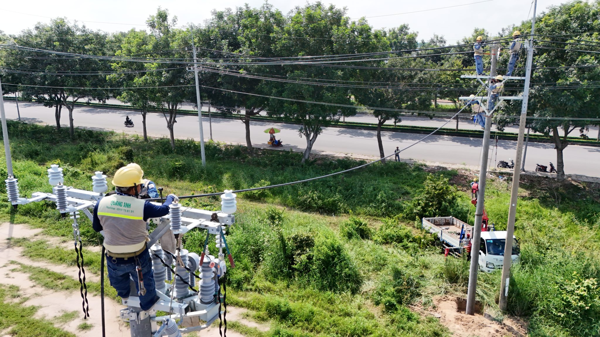
The scope includes 511 m of 150 mm² LV cable and 56 m of 185 mm² LV cable; the pulling method and acceptance must include mechanical protection and electrical testing. [14][11]
On site, verify the actual pulling route parameters: number of pull points, distance between pull points, number and radius of bends, tray/duct heights and the availability of pulling equipment. These parameters determine the pulling method (manual pull, block & tackle, or powered winch) and the cable placement on trays/ducts.
Mechanical protection and storage must suit operating conditions: use trays, ducts or armoured cable where mechanical risk exists; warning tape and protection at buried sections; secure the cable at change-of-direction points. During acceptance or maintenance inspect protective layers and fastening at anchors as an indicator of workmanship quality.
- Pre-pull checks: verify cable parameters, mark the route, inspect accessories (pull ropes, ducts, trays, warning tape).
- Controls during pulling: monitor pulling tension, number of wraps on the pulley, pulling speed and log each pull point.
- Post-installation tests (acceptance/trial run): insulation resistance (IR), continuity checks, phase verification and termination inspection, mechanical checks at cable ends and anchors.
Summary of cable quantities per project documents:
| Cable type | Length |
|---|---|
| LV cable 150 mm² | 511 m |
| LV cable 185 mm² | 56 m |
Outstanding items to clarify before finalising the installation method include maximum allowable pulling tension per cable catalogue, tray/duct diameters, actual number and bend radii, and burial/underground conditions if applicable. If any of these parameters are missing, perform a detailed site survey before choosing the pulling method or protective materials.
Operational warning: do not exceed the cable’s maximum pulling tension and isolate power completely before acceptance tests. Keep test logs and acceptance reports at the site as evidence for final documentation and trial runs.
Installing the 400kVA transformer, connections and technical checks
Procedure for receiving and crane-installing the Thibidi 400kVA transformer (received/installed 18/06/2021), MV-LV connections and mandatory checks before acceptance and energisation.
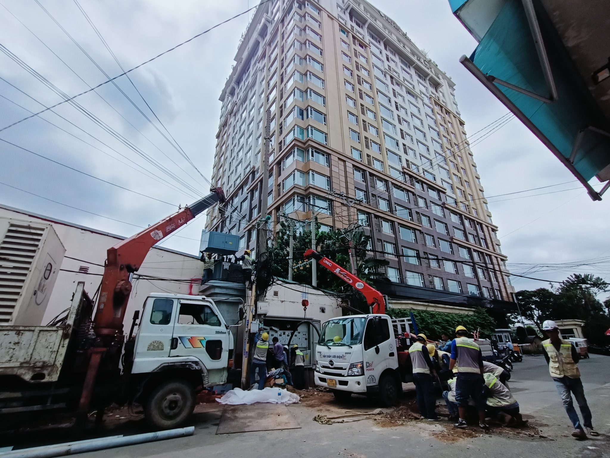
Receipt and installation of the Thibidi 400kVA transformer was performed on 18/06/2021; subsequent steps focused on delivery paperwork, crane lifting, connections and safety checks prior to acceptance. [3][9]
Before lifting and handling check accompanying documents (dispatch note, labels/serial), the physical condition of the enclosure and oil/pad where applicable, and prepare a signed receipt report by both parties. On site verify the transformer foundation, provide spill containment, and confirm drainage around the transformer pad.
MV-LV connections must follow the manufacturer’s connection diagram and the construction drawings; at site remove paint at contact areas, torque bolts per technical requirements, and use conductive grease if specified by the manufacturer or drawings.
Pre-work safety includes lockout/tagout of related power sources, posting warning signage, providing appropriate PPE for workers and confirming absence of dangerous voltages before touching termination points. In maintenance or installation shifts record the personnel and witnesses on the work report.
- Mandatory pre-acceptance tests: insulation resistance (IR) — phase–phase and phase–earth, earthing resistance measurement, R0/neutral earth resistance if required by the grounding scheme, ratio & polarity tests, insulation resistance checks and preliminary relay protection tests.
- Test documentation: all test reports must record instrument make/model/serial, weather conditions, test personnel and witnesses following the prescribed template.
If tests reveal values outside design limits (e.g. earthing resistance higher than required), corrective actions during acceptance should include enhancing earthing, adding rods or supplementary connections, then retesting before energisation. Record all remedial actions in the acceptance report for future maintenance reference.
For industrial substations coordinate with the local distribution utility/EVN for energisation acceptance to ensure network safety and procedural compliance. After acceptance include site logbook, installation acceptance, test reports and updated wiring diagrams in the handover package for operation and maintenance.
Operational warning: before any termination operation perform lockout/tagout and verify by measurement; if earthing is insufficient do not energise until corrected and retested. Energisation must be supported by a complete acceptance report and confirmation of coordination with the network operator.
Next steps: collect all acceptance documentation and plan initial operation activities, including post-energisation inspection schedule and monitoring parameters for the early operation period.
Acceptance, energisation 26/06/2021, handover and results
The energisation milestone for the 400kVA station is confirmed as 26/06/2021 15:00; sequence of acceptance checks pre/post energisation and the handover documentation list are provided.
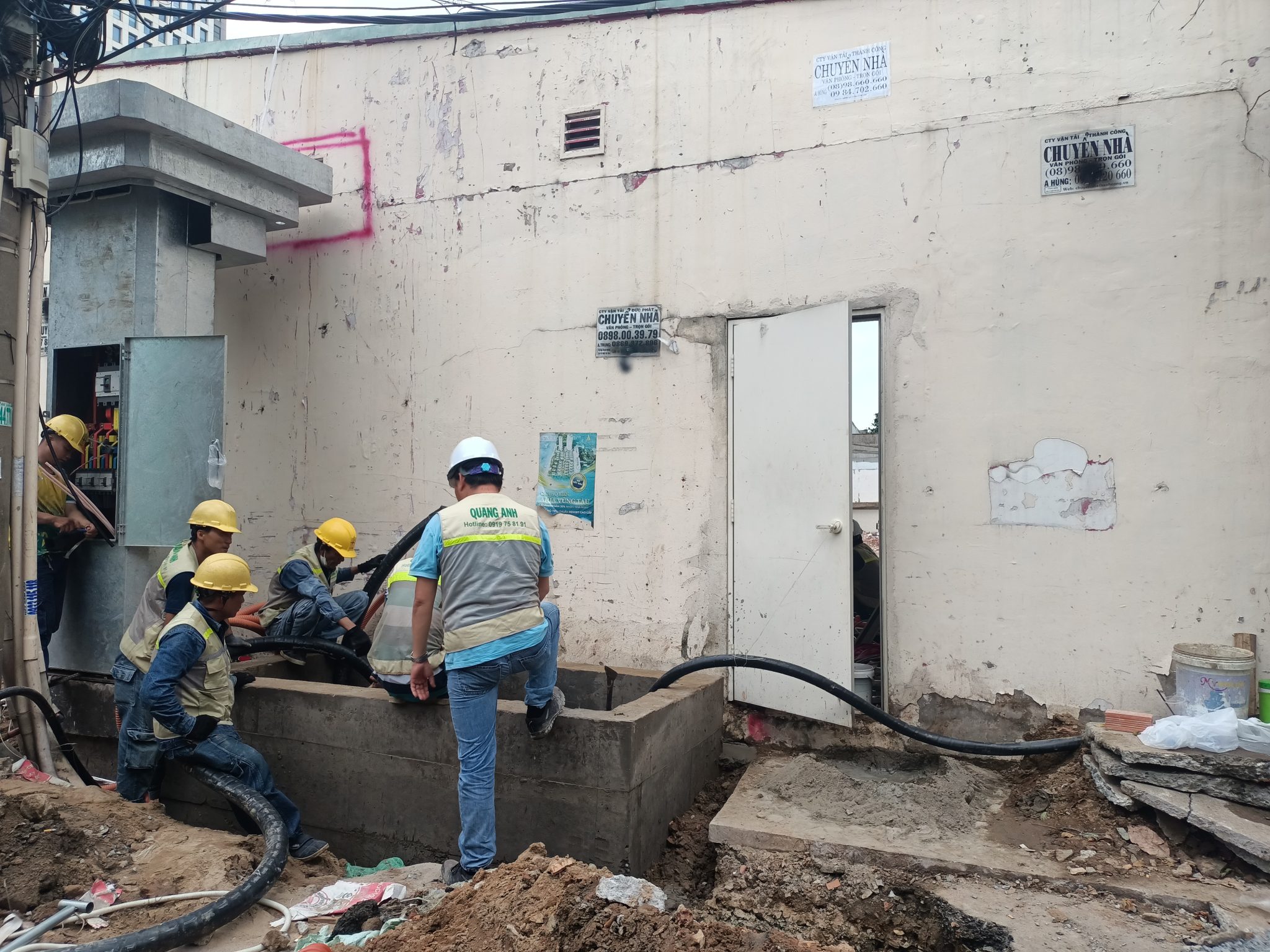
The energisation milestone is confirmed as 26/06/2021 at 15:00 per the historical project data; total project duration was recorded as 30 days with 4 days of actual on-site works. On site the acceptance reports, energisation record and handover minutes are mandatory records for the operation file. [0][0]
Before energisation perform comprehensive acceptance tests; during maintenance or site survey the minimum items include:
- Mechanical checks: torque bolts, secure frames, confirm no foreign objects inside panels and adequate ventilation clearances.
- Cable joint and continuity checks, winding resistance, earthing resistance and insulation resistance (megger) tests for busbars and cables.
- Protection relay and monitoring system checks, and confirmation that protection logic matches the secondary wiring diagram.
- Confirmation of permits/work permits, occupational safety acceptance and network connection permission from the distribution utility.
No-load energisation tests should follow the procedure: phase sequence verification, no-load switching and measure phase voltages immediately after energisation. After initial energisation record the first operation log including no-load current, phase voltages, switchgear status and any relay alarms; record all measurements in the energisation report.
The handover package to the investor must include at least the following items stored in both hard copy and electronic (PDF): logbook, acceptance reports, energisation report, secondary wiring diagrams, equipment list and certificates, operating parameters, maintenance instructions, as-built drawings and equipment warranties. Acceptance sign-off should be by representatives of the investor, contractor, consultant and the distribution utility.
If a capacitor bank/PFC cabinet is present, the acceptance report must state its on/off status, position in the secondary wiring diagram and operating threshold settings (cosφ). Post-energisation risks to note include phase imbalance, overcurrent, capacitor switching faults and sensitive relay trips; have load shedding procedures and emergency action plans ready to handle incidents at site.
Archive acceptance documentation and energisation reports in the project filing system, and schedule routine maintenance and post-acceptance inspections according to the handed-over equipment list.
The project provided a stable power source for Phu Viet Rubber’s production; the attached reports and checklists help the investor prepare documentation, perform acceptance and coordinate with the contractor. Original documents and construction evidence should be archived for maintenance and post-handover inspections.
Frequently asked questions
Which types of factory are suitable for a 400kVA transformer?
A 400kVA station is typically suitable for small-to-medium plants with significant motor loads (compressors, motors, conveyors) that require a dedicated supply to avoid voltage drop and overload. To confirm suitability provide a load list, ratings of major equipment, power factor and contingency requirements so the contractor can calculate sizing.
Why pull LV cables from the transformer to workshops?
Pulling LV cables to distribution points in workshops reduces voltage drop, allows dedicated protection/disconnection per branch, simplifies maintenance and increases operational reliability. Before quoting determine route length, receiving points, expected load at each endpoint and mechanical protection/route requirements.
What is the role of the 630A MCCB in the 400kVA station?
The 630A MCCB acts as the main switch: it isolates the supply, provides overload and short-circuit protection for the LV system. Before acceptance verify model, characteristic curves, trip settings, coordination with relays and mechanical/electrical contact condition.
How does a 160kVAr PFC cabinet help the plant’s power system?
A 160kVAr PFC cabinet improves power factor, reduces reactive power drawn from the grid, lowers losses and stabilises voltage, also helping to avoid reactive power penalties. For accurate design measure current power factor, define the target cosφ and choose the control method for the PFC cabinet.
What should be accepted when commissioning a 400kVA station?
Acceptance includes: checking equipment delivery documentation and receipt reports, mechanical checks and torqueing, wiring and insulation checks, insulation resistance measurements, earthing resistance, protection relay checks and no-load energisation tests. All results must be recorded in acceptance minutes and as-built drawings.
What should the investor prepare when requesting a quote for a 400kVA substation?
Prepare a load list and projected power for the workshops (main loads and major motor ratings); provide proposed transformer location (lot coordinates, site plan) and the 22kV connection point if known. Check site access/transport conditions, provide required permits and the list of acceptance requirements per EVN/local utility, specify desired equipment parameters and a target energisation timeline for the contractor to prepare survey, design and a detailed proposal.
Investor checklist before requesting a quote/works for a 400kVA station
- Prepare expected capacity and load information for the workshops (major load list, large motor ratings).
- Provide the proposed transformer siting (lot coordinates, site plan) and the 22kV connection point if available.
- Check site access for equipment transport: crane staging area, crane parking and required wall cut-outs.
- Prepare legal/permit documents and the list of acceptance requirements per EVN/local utility.
- Request technical documentation for main equipment: transformer specs, MCCB, PFC cabinet, cable types and earthing method.
- Define the desired energisation timeframe and be ready to coordinate outages if needed.
- Prepare internal budget/approvals to proceed with detailed survey and contract signing.
To request detailed technical files or a survey/quotation, please contact the Quanganhcons technical team — we support site assessment and prepare construction schemes tailored to your project.
References (18)
Reference principle: all technical facts, timeline and equipment lists in this article must be based on verified project data or public sources from Quanganhcons / thicongtrambienap listed in the attached documents. When citing legal requirements or standards prefer EVN, Ministry of Industry and Trade circulars, QCVN/TCVN, IEC/IEEE; every claim must include a traceable source. Avoid manufacturer blogs or unofficial sources unless verified; do not provide costs without verified data.
-
Pho bien huong dan ap dung TCVN ve Xe dien
Official TCVN source used to verify technical or regulatory references mentioned.
-
tcvn.gov.vn
Official TCVN source used to verify technical or regulatory references mentioned.
-
AP012025
Standards/regulatory document used to compare technical requirements.
-
Legal guidance on electricity tariffs / three-tier pricing context | Government portal
Official government source used to verify context on connection and tariff topics.
-
MOIT circular and QCVN amendments
Official source used for technical/regulatory cross-checks.
-
Circular on issuing and implementing technical standards
Official source used for technical/regulatory cross-checks.
-
TCVN bulletin
Standards/regulatory reference for technical requirements.
-
Warnings about safety risks from poor quality electrical installations
Used to verify safety recommendations in the article.
-
TBT agreements and basic legal contents on technical barriers
Standards/regulatory references for technical compliance.
-
Improving construction technical standards system
Standards/regulatory references.
-
Urgent completion of standards for EV charging infrastructure
Standards/regulatory references.
-
Experience improving productivity & quality at PC Quang Ngai
Used as a reference for operational procedures.
-
Local technical standards for water quality
Technical/regulatory cross-checks.
-
Standardisation and safety management for installation devices
Standards/regulatory references used in the article.
-
Online forum on sustainable recovery and development post-COVID
Contextual reference.
-
National standards publishing cooperation
Standards/regulatory references.
-
Vietnam Standards and Quality Institute — 40 years
Standards/regulatory reference.
-
Government datafiles — planning and connection documents (example)
Official source for planning and connection documentation references.
Substation budget estimate
Select the capacity, route lengths and package to view your indicative budget and electrical parameters.
Request a project quotation
Send your project details, BOQ or drawings to request a formal quotation. Fields marked * are required.
Quotation scope
Applies to one EVN-supplied substation with oil-immersed transformers at 22/0.4 kV (single-phase: 12.7/0.23 kV), with MV metering VTs/CTs supplied by EVN. The estimate includes the selected equipment, installation, earthing, transformer-to-main-breaker connections, design and connection documentation, and coordination of testing and utility acceptance.
Kiosk, integrated steel-pole and indoor substations include MV switchgear and the entered underground cable route. Other outdoor arrangements use the relevant protection configuration. The final diagram must meet the project connection requirements.
Excludes VAT, cables from the substation switchboard to the MSB/loads, live-line work, harmonic reactors, weak-ground treatment or special piling, land and special fire-protection provisions. Underground routes assume normal construction conditions and exclude road drilling and special reinstatement.
Prices are indicative investment budgets. A formal quotation follows site assessment and agreement on the configuration. Electrical selections are preliminary and require design verification before installation.
Capacity range and application conditions
The catalogue defines the enquiry range of this tool, not universal TCVN capacity limits. Single pole-mounted transformers: 15–100 kVA; three-unit banks: 3×15–3×100 kVA. Platform substations: 100–630 kVA. Steel-pole substations: 100–630 kVA; 750/800 kVA require design verification and local approval. Ground-mounted, kiosk and indoor configurations: 50–10,000 kVA. Not every configuration has a package price or the same structural design.
Reference: EVN Decision 1299/QD-EVN dated 3 November 2017, Volume 1, sections 3.3–3.4. Check the current requirements of the responsible utility before implementation. Kiosks must meet manufacturer ratings and testing requirements (IEC 62271-202); indoor and ground-mounted arrangements must meet project layout, ventilation, structural and fire-protection requirements. For multiple transformers, specify the quantity and capacity of each unit.
Developed by QuangAnhcons · © 2026 QuangAnhcons. Code licensed under GPL-2.0-or-later. Standards and manufacturer data belong to their respective owners.