Tiếng Việt
 简体中文
简体中文 Deutsch
 日本語
日本語 한국어
한국어 ไทย
ไทย Русский
 Français
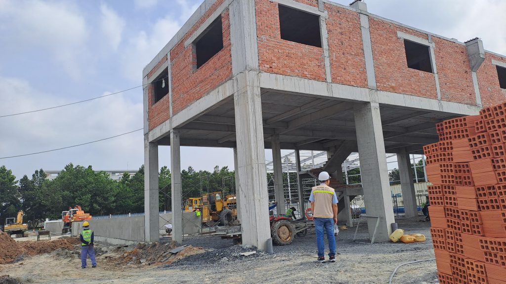
In the factory construction permit application, there are several important types of drawings such as floor plans, sections, elevations, position, and electrical systems. Each type of drawing provides necessary information to fully and accurately visualize the project design.
Overview of Floor Plans
The floor plan includes overall and preliminary plans, showing the building area compared to the land area and the layout from the ground to the roof. It is a fundamental factor in determining the suitability with the building density of the area.
The floor plan is an important component in architectural design, showing the overall layout of the internal space through cross-sectional projection. It is designed at a height from 1.5 to 1.8 meters above the floor to clearly describe the construction floor plan. The floor plan includes key elements such as room positions, stairs, entrances, and landscapes, helping to easily visualize the building layout and interior design.
- Concept: This is an important cross-sectional projection showing the distribution of interior space within a floor. It specifically illustrates rooms like living rooms, kitchens, bedrooms, along with bathrooms and special areas like corridors or balconies.
- Role: The floor plan is a powerful tool helping stakeholders like engineers and architects clearly grasp the necessary details for effective construction and interior design.
- Drawing scale: Common scales range from 1/100 to 1/500 depending on the project’s size. Especially, the overall site plans can use expanded scales such as 1/200, 1/500, or even 1/1000 to provide a comprehensive view of the project’s location and related factors on the construction site.
- Classification: Each floor will have a separate floor plan to ensure detail and accuracy. The overall floor plan is usually used to present the entire project site, serving as a tool to clearly and intuitively display the entire content.
- How to read: When studying a floor plan, recognizing and distinguishing furniture symbols along with the installation positions of technical elements is crucial. This helps in easy management and navigation during the interior design and actual construction process.
- Relationship: To fully visualize the project, the floor plan needs to be used concurrently with the elevation and section drawings. These drawings provide supplementary information on height and overall structure to ensure consistency and completeness of the design.
The combination of these drawings provides clear orientation from the design stage to execution, optimizing the management and supervision process. Thus, the overall floor plan not only optimizes the building layout scientifically but also facilitates execution and progress checking.

Detailed Section and Elevation Drawings
Section drawings depict the inner architecture when vertically slicing through space, usually showing foundations and septic tanks. Meanwhile, elevation drawings display the factory facade, from the shape to the height of each floor, providing an overall look at the exterior design.
In the fields of construction and energy, elevation and section drawings are two essential components in a project’s technical documentation. These two types of drawings clearly present not only the exterior shape but also detailed internal structures of the project.
Elevation drawings are projections of the building when viewed vertically from directions like front, back, left, or right. These drawings help depict the building’s aesthetics through details such as the main entrance, windows, roofs, and external decorative structures. With the characteristic of a section parallel to the vertical projection plane, architectural drawings not only show shape, size, and height scale but also provide information about balanced layout and harmonious design of the structure.
Section drawings, on the other hand, are created when using one or multiple imaginary planes to cut vertically or horizontally through the structure. These drawings show detailed structures and components inside like floors, roofs, stairs, chimneys, underground water levels… Simultaneously, the vertical or horizontal section aids engineers in easily checking and accurately determining internal structure details through accurate dimensions and specifications.
The biggest difference between elevation and section drawings lies in the projection direction and the specific content they depict. While elevation drawings focus on the external shape from all projection directions, including the building’s aesthetics, section drawings delve into technical details, clearly laying out the internal spatial structure.
The application of these types of drawings in reality helps experts and contractors easily evaluate design and carry out precise construction. For professional readers like engineers and leaders, understanding elevation drawings requires attention to wall axes and viewing directions, whereas reading section drawings necessitates focus on height dimensions of components and the relationship between technical elements.
Thanks to these detailed drawings, designers and constructors can early detect design errors, optimize preparation and execution work, ensuring the project is completed both aesthetically and functionally.

Electrical and Plumbing
Electrical system drawings include the installation locations of electrical consumption devices such as sockets, switches, and lights. Plumbing drawings record the schematic of clean and wastewater pipe systems, as well as the positions of sanitary devices and water treatment systems.
Electrical and plumbing systems are two foundational pillars in construction projects, ensuring they not only provide electricity and domestic water but also treat wastewater, providing convenience and safety to users.
Plumbing systems include main components:
1. Water supply system:
- Water source: Can be sourced from surface water, groundwater, or recycled water.
- Water pipes: Conduct water from the source to the building, via pumping stations.
- Pumping station: Includes pumps, water tanks, and float devices for automatic water cut-off control.
- Distribution pipe network: Connects tanks to each area.
- Hot and cold water supply system: Includes direct or indirect cold water supply, hot water supply via local or centralized systems like boilers, heat pumps, solar energy.
- Accessories: Include gate valves, butterfly valves, check valves, Y filters, and couplings.
2. Drainage system:
- Natural drainage (rainwater) and domestic wastewater drainage.
- Includes components like wastewater pipes, siphons, gully traps.
- Wastewater pipes are designed to prevent debris, blockages, with regular inspection and maintenance.
- Ensure clear separation of domestic wastewater and rainwater.
- Sewer system includes wastewater pipes, ventilation, and underground drains.
This system ensures the sufficient supply of high-quality water, effective wastewater collection and treatment, protecting health and the environment.
Electrical systems in construction projects:
- Provide lighting, household electricity, and power equipment operation.
- Include transformers, backup generators, switchboards, conductors, lighting lamps, sockets, breakers, and protective devices.
- Integrate with backup lighting and lightning protection systems to ensure safety and continuity.
- Construction and maintenance must comply with technical and national standards.
Standards and regulations:
- National technical standards like TCVN 13606:2023, TCVN 4037:2012, TCVN 4038:2012, TCVN 7957:2008, TCXDVN 51:2008, TCXDVN 33:2006 are crucial for design and construction.
Design and construction:
- System design requires setting up schematic diagrams, correctly positioning components like tanks, pumps, and pipes.
- Electrical systems need to clearly differentiate between supply sources and distribution networks.
- Construction requires strict quality control and routine maintenance to ensure stable operation.

Perspective and Mapping Requirements in Construction
3D perspectives provide a visual overview, helping investors easily envision the entire project. Sometimes, current maps are necessary to accurately depict the land’s position when the land use right certificate lacks coordinates.
Perspective plays a crucial role in construction and architectural projects. A 3D perspective image not only simulates the three-dimensional space of a project from various angles but also provides an overall view of the design. This helps stakeholders, from investors to contractors, in assessing feasibility and clearly imagining locations, styles, and actual sizes in space.
Mapping and drawing requirements in construction are indispensable. Maps such as 1/500, 1/2000, and 1/5000 scale planning maps play essential roles in construction planning. The 1/2000 planning map is often used for detailed zoning planning, while the 1/500 map is a mandatory document for approving specific projects, even necessary for construction permits.
Moreover, location maps clearly define the plot’s position and relationships with neighboring areas. They must be created in accordance with current standards and technical regulations, ensuring not only high accuracy but also legal validity.
Architectural drawings provide a more detailed view of the project’s overall structure, including floor plans, elevations, and sections. These drawings are not only essential documents for architectural design but also critical factors in obtaining construction permits and executing construction processes. In particular, construction drawings require specifying details from materials to processing and on-site execution guidance.
Architectural design must be accompanied by a complete design dossier, which includes the basic design, technical design, and construction drawings. All must comply with national standards like TCVN 5671:2012 and relevant legal provisions.
Finally, important concepts like red lines and construction lines must be clearly defined in maps and drawings to ensure land use rights and avoid potential legal issues.

The types of drawings in the factory construction permit application are important tools that help ensure technical feasibility, optimize investment, and secure long-term development strategies for the project.
For more details and free consultation, please call QuangAnhcons at Hotline: +84 9 1975 8191.
QuangAnhcons provides professional construction drawing consulting and documentation services, ensuring all project requirements for high-quality industrial and construction projects are met.